How can we help?
Having trouble? Click here to access our troubleshooting guide.
Your Question:
Xtrafast 96 E1 - Xtrafast 120 E1 Engineer Support
Welcome to the Engineer Technical Support section. Please use the different sections below to find answers to your technical questions. You can also find a range of useful contact numbers, including Technical support, here.
Fault Finding Information
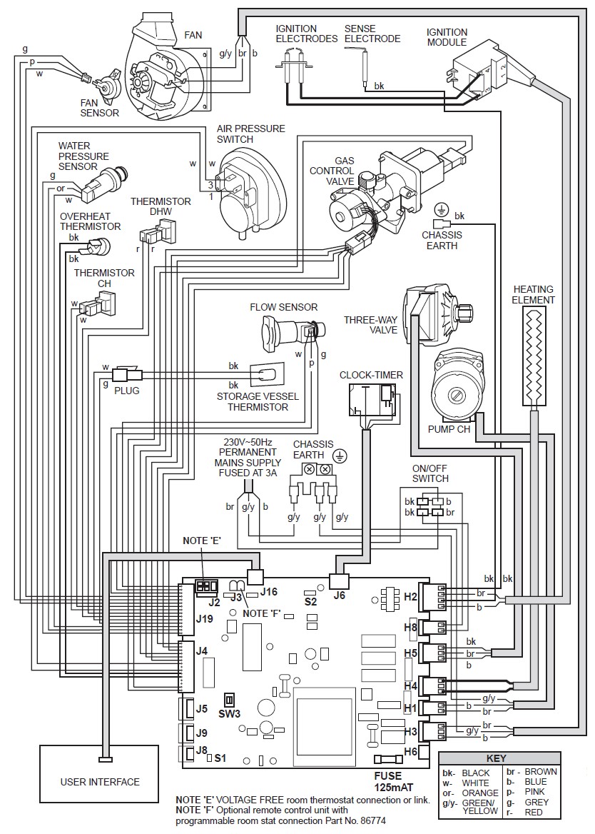
Wiring Diagram
Component Tests
Pump – 230vac across Pins 1 (Brown) & 2 (Blue) on connection H1 on the Main PCB
Fan – 230vac across Pins 3 (Brown) & 1 (Blue) on connection H3 on the Main PCB
Diverter Valve Motor (Domestic Hot Water Mode) – 230vac across Pins 1 (Blue) & 3 (Black) on connection H5 on the Main PCB (the Motor Spindle should drive out) OR remove the Diverter Valve Motor Plug from the Motor and test voltages shown as below with a Domestic Hot Water Demand:

Diverter Valve Motor (Central Heating Mode) – 230vac across Pins 2 (Brown) & 3 (Black) on connection H5 on the Main PCB (the Motor Spindle should retract) OR remove the Diverter Valve Motor Plug from the Motor and test voltages shown as below with a Central Heating Demand:

Spark Generator Input from Main PCB – 50vac across Pins 3 (Brown) & 1 (Blue) on connection H2 ZIG on the Main PCB, or across the 2 pins on the end of the Spark Generator Plug on demand (with the feed plug removed from the Spark Generator)
Air Pressure Switch (AT REST) – 35vdc on Pin 7 (White) to an Earth on connection J4 on the Main PCB (Common contact 1 on APS) and 0vdc on Pin 9 (White) to Earth on connection J4 on the Main PCB (N/O contact 3 on APS)
Air Pressure Switch (MADE) – 32vdc on Pin 7 (White) to an Earth on connection J4 on the Main PCB (Common contact 1 on APS), and 32vdc on Pin 9 (White) to Earth on connection J4 on the Main PCB (N/O contact 3 on APS) when the Fan is running
Overheat Thermostat – 32vdc on Pin 10 (Black) to Earth and Pin 11 (Black) to Earth on connection J4 on the Main PCB on demand (The Overheat Thermostat will only become live during a demand, and will show 0vdc when the appliance is in standby mode) The Overheat Thermostat can also tested for continuity with the power off.
Gas Valve (Main Solenoid) – 22vdc - 24vdc across Pins 15 (Grey) and 14 (White) on connection J4 (during spark generation) to open the Main Solenoid, then drops to approximately 11vdc – 13vdc to maintain the flame.
Water Pressure Sensor
5vdc to Earth on Pin 13 (Orange) on connection J19 on the Main PCB – Feed from the Main PCB to Water Pressure Sensor
1vdc @ 0bar, 1.5vdc @ 1bar, 3vdc @ 3bar to Earth on Pin 14 (White) on connection J19 on the Main PCB – Feedback from the Water Pressure Sensor
0vdc to Earth on Pin 15 (Grey) on connection J19 on the Main PCB – This is a negative (neutral)
User Interface (Display) PCB Test
All measured to Earth from left to right on connection J16 on the Main PCB (All Grey Wires)
Pin 1 - 0vdc
Pin 2 - 5dc
Pin 3 - 3.7vdc – 4.4vdc (ranging)
Pin 4 – 4.3vdc – 4.8vdc (ranging)
NOTE – All the above voltages are from the Main PCB to the User Interface (Display) PCB
Storage Cylinder Heating Element – 230vac - 1.8Kohms
Domestic Hot Water NTC Thermistor – 12Kohms @ 20 degrees celsius
Central Heating NTC Thermistor – 12Kohms @ 20 degrees celsius
Storage Cylinder NTC Thermistor – 12Kohms @ 20 degrees celsius

Domestic Hot Water Flow Sensor Test (Using Onboard Diagnostic Menu)

Press and Hold the “Display Backlight” button on the left hand side of the display for 5 seconds (Key Number 8 on the diagram above) until the digital display shows ”01” on the RIGHT hand side of the display.
Change the “01” to “07” using the Domestic Hot Water PLUS key
The figure on the LEFT hand side of the display will show the domestic hot water flow rate in litres per minute and will show “00” with the hot tap OFF (which means 0 litres a minute)
With the hot tap ON it should show a figure between 10 and 199. Whatever number is shown, divide it by 10 and this will be the litres per minute being read by the domestic hot water flow sensor (For example: if the number is 96 it will equate to 9.6 ltrs/min.)
If the number still shows “00” with the hot tap open, the domestic hot water flow sensor is not functioning.
Domestic Hot Water Flow Sensor Test (Voltage Test Using A Multimeter)
Tap Off
18vdc to Earth on Pin 1 (White) on connection J19 on the Main PCB – Feed from the Main PCB to the Domestic Hot Water Flow Sensor
12vdc to Earth on Pin 2 (Pink) on connection J19 on the Main PCB – Signal from the Domestic Hot Water Flow Sensor *NOTE - This may read 0vdc on occasion depending on where the Hall Effect Turbine has stopped in the Flow Sensor
0vdc to Earth on Pin 3 (Grey) on connection J19 on the Main PCB – This is a negative (neutral)
Tap On
18vdc to Earth on Pin 1 (White) on connection J19 on the Main PCB – Feed from the Main PCB to the Domestic Hot Water Flow Sensor
5vdc – 7vdc to Earth (ranging up and down when the tap is running) on Pin 2 (Pink) on connection J19 on the Main PCB – Signal from the Domestic Hot Water Flow Sensor
0vdc to Earth on Pin 3 (Grey) on connection J19 on the Main PCB – This is a negative (neutral).
Fault codes and Reasons
| Fault Codes |
Fault Description |
Possible Causes |
| Fan Symbol |
Air Flow Fault/Incompatible Software
|
|
| Fault Code FF00
|
Air Flow Fault/Incompatible Software
|
|
| Fault Code FF02
|
Air Flow Fault (After 40 Seconds)
|
|
| Fault Code FF04 |
Ignition Fault or Flame Detection Error
|
|
| Fault Code FF05
|
The Appliance Has Overheated (Reached 115 Degrees Celsius)
|
|
| Fault Code FF06
|
Central Heating NTC Thermistor Fault
|
|
| Fault Code FF07
|
Domestic Hot Water NTC Thermistor Fault
|
|
| Fault Code FF08
|
Storage Vessel NTC Thermistor Fault
|
|
| Fault Code FF09
|
System Water Pressure Sensor Fault
|
|
| Fault Code FF12
|
User Interface (Display) PCB Fault Or Other Errors NOTE: On Certain Versions This Code Will Appear For A Few Seconds When The Mains Power Is Turned On. This Is Normal Operation.
|
|
| Fault Code FF13
|
Main PCB Fault And Other Errors
|
|
| Fault Code FF14
|
The Central Heating NTC Thermistor Has Reached 97 Degrees Celsius
|
|
| Fault Code FF20
|
Communication Error
|
|
| Lightning Symbol |
Ignition Fault or Flame Detection Error
|
|
| Telephone Symbol |
Boiler Has Locked Out – A Fault Code Will Be Shown On The Digital Display
|
|
| Warning Symbol |
|
|
Available Literature
 Installation and Servicing Manual